Mechanisms
Worm gear
Mechanisms · Gear drives
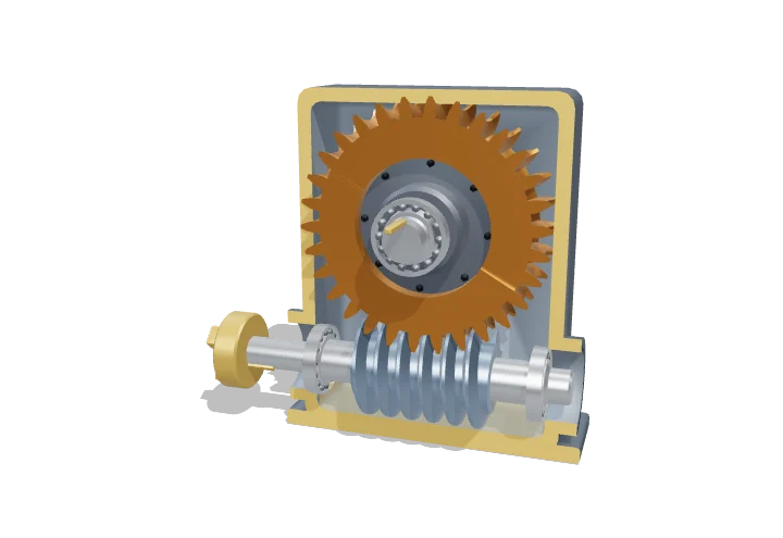 Open the interactive 3D model →
How can a gearbox the size of a shoebox slow a motor down thirty times and hold a heavy gate shut when the power is off?
A worm gear is a screw (the worm) turning a toothed wheel. Each full turn of the screw nudges the wheel round by just one tooth, so a fast motor becomes a slow, strong turn. If the screw thread is shallow enough, the wheel cannot turn the screw backwards — friction holds it.
A worm gear transmits motion between non-intersecting shafts at 90° by a screw (the worm) meshing with a helical, throated wheel, giving reduction ratios of about 5–100 : 1 in a single compact stage. Because the thread slides across the wheel teeth, efficiency depends strongly on the lead angle, and at small lead angles friction can prevent the wheel from driving the worm backwards.
Key facts
- Ratio
- i = wheel teeth ÷ worm starts
- Single-stage ratio range
- ≈ 5 : 1 to 100 : 1
- Lead angles in this model
- 4.8° (1 start) to 18.4° (4 starts)
- Efficiency
- ≈ 50–90 %, rising with lead angle
- Usual materials
- case-hardened steel worm, phosphor-bronze wheel
- Shaft angle
- 90°, axes offset by the centre distance
Parts you can explore (8)
- Worm
- Input shaft
- Worm wheel
- Wheel centre
- Output shaft
- Bearings
- Housing
- Oil bath
In the 3D model
Rotate and take apart the model, follow a guided tour of what each part does and why it’s needed, change it with a live slider, and test yourself with a short quiz. Free, no sign-up.
OpenArc Models’ models are simplified teaching schematics. Terms · Privacy