Power & energy
Wind turbine
Energy · Horizontal-axis wind turbine
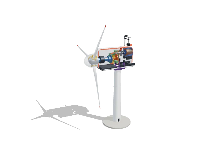 Open the interactive 3D model →
How do three slowly turning blades power thousands of homes — and why don’t they spin faster in a storm?
Wind flowing over the long, curved blades makes them turn, a little like an aeroplane wing being lifted. The slowly turning shaft is sped up by gears and spins a generator, which makes electricity. In very strong winds the blades twist sideways to let the wind slip past, so the turbine is not damaged.
A horizontal-axis wind turbine extracts kinetic energy from the air passing through its rotor disc, using lift on rotating aerofoil blades to make slow, high-torque rotation that a gearbox and generator turn into electricity. Available power rises with the cube of wind speed and the square of rotor diameter, but no rotor can capture more than 16/27 (59.3%) of it — the Betz limit.
Key facts
- This machine
- 3 MW rated, rotor Ø 112 m (swept area ≈ 9,850 m²), hub height 84 m
- Betz limit
- C_p,max = 16/27 ≈ 0.593; best real rotors ≈ 0.45–0.50
- Cut-in / rated / cut-out wind
- 3 / ≈ 10.4 / 25 m/s in the model (typically 3–4 / 11–13 / 25 m/s)
- Rotor speed
- 9–14.2 rpm; tip speed up to ≈ 83 m/s
- Optimum tip-speed ratio (3 blades)
- λ ≈ 7–9
- Capacity factor
- onshore ≈ 25–45%; offshore ≈ 40–55%
Parts you can explore (12)
- Blades
- Hub & spinner
- Pitch system
- Main shaft & bearing
- Gearbox
- High-speed shaft & brake
- Generator
- Bedplate
- Yaw system
- Nacelle
- Wind sensors
- Tower
In the 3D model
Rotate and take apart the model, follow a guided tour of what each part does and why it’s needed, change it with a live slider, and test yourself with a short quiz. Free, no sign-up.
OpenArc Models’ models are simplified teaching schematics. Terms · Privacy