Power & energy
High-bypass turbofan
Propulsion · Gas turbine
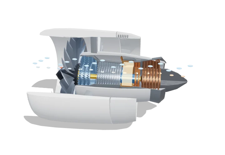 Open the interactive 3D model →
How do two engines push a 250-tonne airliner off the runway — and why is the front of each one a giant fan?
A jet engine sucks air in, squeezes it, burns fuel in it and blasts the hot gas out of the back. In a modern airliner engine that hot gas also spins a huge fan at the front. The fan pushes a much bigger stream of air around the outside of the engine, and that stream makes most of the push.
A high-bypass turbofan is a gas-turbine core — compressor, combustor and turbine running the Brayton cycle — whose turbines also drive a large fan that pushes most of the air around the core. Accelerating a large mass of air modestly is far more propulsively efficient than accelerating a little air very fast, so modern airliner engines get roughly 80 % of their thrust from the bypass stream.
Key facts
- Bypass ratio (model)
- ≈ 9 : 1 at take-off (GEnx-class)
- Overall pressure ratio
- ≈ 40–50 (modern large turbofans)
- Turbine entry temperature
- ≈ 1700–2000 K at take-off
- Spools
- LP (fan + booster + LPT) and HP (HPC + HPT), concentric shafts
- Speeds
- fan ≈ 2500 rpm, HP spool ≈ 11 000 rpm at take-off
- Thrust split
- ≈ 80–85 % from the bypass stream
Parts you can explore (13)
- Nacelle
- Fan
- Bypass duct
- Low-pressure compressor
- High-pressure compressor
- Combustor
- High-pressure turbine
- Low-pressure turbine
- LP shaft
- HP shaft
- Exhaust nozzle
- Thrust reverser
- Airflow
In the 3D model
Rotate and take apart the model, follow a guided tour of what each part does and why it’s needed, change it with a live slider, and test yourself with a short quiz. Free, no sign-up.
Open High-bypass turbofan in 3D →
OpenArc Models’ models are simplified teaching schematics. Terms · Privacy