Electromagnetism & electronics
Single-phase transformer
Electrical · AC voltage change
 Open the interactive 3D model →
How does a box with no moving parts turn 400,000 volts into the 230 volts at your wall socket?
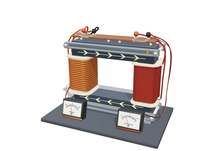
A transformer has two coils of wire wound on one iron loop, and the coils never touch. Alternating current in the first coil makes a magnetic field that keeps flipping, and that flipping field pushes a voltage out of the second coil. The coil with more turns of wire gets the bigger voltage.
A transformer transfers AC power between two electrically separate windings through a shared, time-varying magnetic flux in a laminated iron core. Because every turn on the core links the same flux, the voltage per turn is the same on both windings, so the voltage ratio equals the turns ratio and the current ratio is its inverse.
Key facts
- Ideal relations
- Vs/Vp = Ns/Np = Ip/Is
- EMF equation
- V_rms = 4.44 f N A_c B_max
- Peak core flux density (grain-oriented steel)
- ≈ 1.5–1.7 T (saturation ≈ 2.0 T)
- Efficiency
- ≈ 95–98% (small units); 99.5–99.8% (large power transformers)
- Lamination thickness
- ≈ 0.23–0.35 mm, ≈ 3% silicon steel
- Model default
- Ns/Np = 2 → 460 V rms from 230 V
Parts you can explore (10)
- Iron core
- Primary coil
- Secondary coil
- Flux path
- Coil formers
- Clamps & frame
- Terminals
- Winding leads
- Mounting feet
- Voltmeters
In the 3D model
Rotate and take apart the model, follow a guided tour of what each part does and why it’s needed, change it with a live slider, and test yourself with a short quiz. Free, no sign-up.
Open Single-phase transformer in 3D →
OpenArc Models’ models are simplified teaching schematics. Terms · Privacy