Electromagnetism & electronics
Switch-mode phone charger
Power electronics · Converters
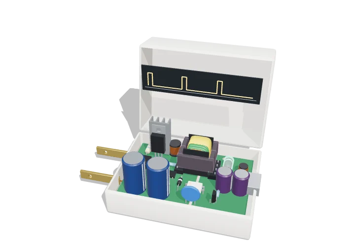 Open the interactive 3D model →
How does a charger small enough to fit in your palm turn 230 volts from the wall into a safe 5 volts?
A phone charger first turns the wall’s alternating current into high-voltage direct current. A tiny electronic switch then flicks that current on and off 65,000 times a second into a small transformer, which hands the energy across to the low-voltage side in little bursts. A light-signal feedback loop keeps adjusting the bursts so the output stays at exactly 5 V.
A phone charger is an offline flyback converter: it rectifies the mains to high-voltage DC, chops that DC at tens of kilohertz with a MOSFET, and uses a small gapped transformer to store energy during each on-time and release it to an isolated, rectified 5 V output during each off-time. Feedback from the output through an optocoupler adjusts the duty cycle so the output stays at 5 V whatever the load or mains voltage.
Key facts
- Input
- 100–240 V AC, 50/60 Hz (“universal input”); 230 V AC gives ≈ 325 V DC
- Output
- 5 V, up to 2 A (10 W) in this model
- Switching frequency
- ≈ 65–130 kHz typical; GaN chargers reach several hundred kHz
- Duty cycle
- ≈ 5–15 % at 230 V input in this design, rising with load
- Efficiency
- ≈ 80–88 % at full load for a 10 W charger
- No-load power
- < 0.1 W (US DoE Level VI / EU ecodesign limits)
Parts you can explore (11)
- Charger case
- AC input
- Bridge rectifier
- Bulk capacitor
- Switching MOSFET
- Flyback transformer
- Optocoupler feedback
- Output rectifier and filter
- USB output
- Circuit board
- Gate waveform
In the 3D model
Rotate and take apart the model, follow a guided tour of what each part does and why it’s needed, change it with a live slider, and test yourself with a short quiz. Free, no sign-up.
Open Switch-mode phone charger in 3D →
OpenArc Models’ models are simplified teaching schematics. Terms · Privacy