Electromagnetism & electronics
RC servo motor
Electromechanics · Control
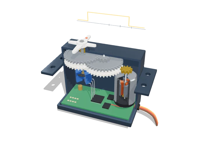 Open the interactive 3D model →
How does a robot arm or model plane know exactly how far to turn — and stay there?
A servo is a little box with a motor, some gears and a sensor that measures where the output shaft is pointing. You tell it the angle you want with a short electrical pulse. A circuit keeps comparing where the shaft is with where it should be, and drives the motor until the two match.
A hobby servo is a complete position-control system in a small box: a DC motor, a reduction gear train, a potentiometer that measures the output angle, and a control board that compares that angle with a command encoded as the width of a repeating pulse. The board drives the motor in whichever direction reduces the error, so the output shaft moves to, and holds, the commanded angle.
Key facts
- Command signal
- Pulse every ≈ 20 ms (50 Hz); width 1.0–2.0 ms, 1.5 ms = centre
- Travel
- Typically ≈ 90–120° for 1.0–2.0 ms; up to ≈ 180° with extended pulses
- Supply
- 4.8–6.0 V (high-voltage types to 7.4–8.4 V)
- Gear reduction
- ≈ 100 : 1 to 400 : 1 (≈ 168 : 1 in this model)
- Stall torque
- ≈ 0.3–1.5 N·m (3–15 kg·cm) for standard-size servos
- Transit speed
- ≈ 0.1–0.2 s per 60° at no load
Parts you can explore (10)
- Servo case
- Gear housing
- DC motor
- Gear train
- Output shaft
- Servo horn
- Feedback potentiometer
- Control board
- Servo cable
- PWM signal
In the 3D model
Rotate and take apart the model, follow a guided tour of what each part does and why it’s needed, change it with a live slider, and test yourself with a short quiz. Free, no sign-up.
OpenArc Models’ models are simplified teaching schematics. Terms · Privacy