Fluids & heat
Centrifugal pump
Fluid machinery · End-suction pump
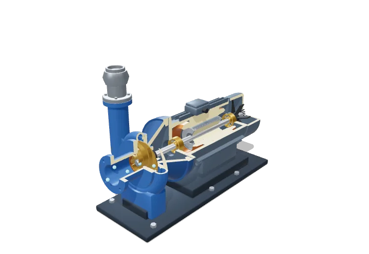 Open the interactive 3D model →
How does a spinning wheel push water up to the top floor of a building?
A motor spins a wheel with curved blades, called the impeller, inside a snail-shaped casing. Water enters at the centre and is flung outward, gaining speed. The widening casing then slows the water down, and its speed turns into pressure that pushes it up the pipe.
A centrifugal pump adds energy to a liquid by spinning it in an impeller, raising its angular momentum, and then converts the resulting velocity into pressure in the volute. Its behaviour is captured by the Euler turbomachine equation, the pump curve (head versus flow), the affinity laws for speed changes and the NPSH requirement that keeps the eye free of cavitation.
Key facts
- Model rated point
- 25 m³/h at 32 m head, 2900 rpm, η ≈ 0.65 → ≈ 3.4 kW shaft power
- Typical motor speeds
- ≈ 1450/2900 rpm (50 Hz), 1750/3500 rpm (60 Hz)
- Affinity laws
- Q ∝ N, H ∝ N², P ∝ N³
- Best efficiency
- ≈ 40–70% small pumps; 80–90% large pumps
- Water vapour pressure
- 2.34 kPa at 20 °C; 47.4 kPa at 80 °C
- Preferred operating region
- ≈ 70–120% of best-efficiency flow
Parts you can explore (11)
- Impeller
- Volute casing
- Inlet (eye)
- Discharge pipe
- Adaptor bracket
- Shaft
- Mechanical seal
- Shaft bearing
- Motor
- Base feet
- Water flow
In the 3D model
Rotate and take apart the model, follow a guided tour of what each part does and why it’s needed, change it with a live slider, and test yourself with a short quiz. Free, no sign-up.
OpenArc Models’ models are simplified teaching schematics. Terms · Privacy