Electromagnetism & electronics
Three-phase induction motor
Electromagnetism · Motors
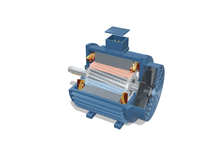 Open the interactive 3D model →
How can a motor spin with no wires, magnets or brushes connected to the part that turns?
In an induction motor, three sets of copper coils around the outside take turns being magnetised, so their magnetic field spins round like a whirlpool. That moving field pushes electric currents through metal bars in the rotor in the middle, and those currents get dragged along by the field. The rotor always turns a little slower than the field — that small lag is what keeps the currents, and the turning force, going.
A three-phase induction motor uses balanced currents in a distributed stator winding to create a magnetic field of constant strength that rotates at synchronous speed, 120f/p. The squirrel-cage rotor turns slightly slower than that field, and the resulting slip induces currents in the cage bars whose interaction with the field produces torque.
Key facts
- Synchronous speed
- n_s = 120f/p: 1500 rpm for 4 poles on 50 Hz (1800 rpm on 60 Hz)
- Rated slip
- ≈ 1–5 %; about 4 % for a 4 kW motor (≈ 1440 rpm)
- Efficiency
- ≈ 87–90 % at 4 kW (IE3 class), > 95 % above ≈ 200 kW
- Starting current
- ≈ 6–8 × rated current direct-on-line
- Power factor
- ≈ 0.8–0.85 at full load, much lower at no load
- Share of use
- Electric motors use roughly 45 % of the world’s electricity; most are induction motors
Parts you can explore (12)
- Stator frame
- Stator core
- Stator windings
- Rotating magnetic field
- Rotor core
- Squirrel cage
- Shaft
- Bearings
- End shields
- Cooling fan
- Fan cowl
- Terminal box
In the 3D model
Rotate and take apart the model, follow a guided tour of what each part does and why it’s needed, change it with a live slider, and test yourself with a short quiz. Free, no sign-up.
Open Three-phase induction motor in 3D →
OpenArc Models’ models are simplified teaching schematics. Terms · Privacy