Fluids & heat
Hydraulic cylinder
Fluid power · Linear actuator
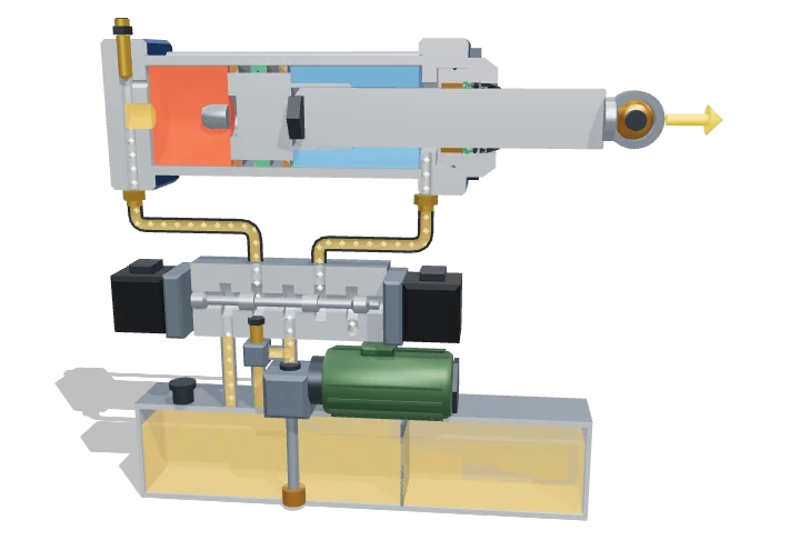 Open the interactive 3D model →
How can a steel tube the width of your hand push with the weight of five cars?
A hydraulic cylinder is a tube with a piston inside. A pump pushes oil into the tube behind the piston, and the oil’s pressure shoves the piston and its rod out with enormous force. Send the oil to the other side and the rod pulls back in.
A double-acting hydraulic cylinder turns oil pressure into a straight-line push or pull: force is pressure times the area the oil acts on, and speed is the pump flow divided by that same area. A directional control valve chooses which side of the piston is pressurised, while seals, a gland and end cushions make the actuator leak-tight, guided and gentle at the end of its stroke.
Key facts
- Bore / rod (this model)
- 63 mm / 36 mm, stroke 100 mm
- Piston areas
- 31.2 cm² cap side, 21.0 cm² annulus (ratio φ ≈ 1.49)
- Maximum force at 160 bar
- ≈ 49.9 kN extending, ≈ 33.6 kN retracting
- Speed at 20 L/min
- ≈ 10.7 cm/s extending, ≈ 15.9 cm/s retracting
- Typical working pressure
- ≈ 160–250 bar industrial, up to ≈ 350 bar mobile
- Typical piston speed
- ≈ 0.05–0.5 m/s (seals usually rated ≤ 0.5–1 m/s)
Parts you can explore (16)
- Barrel
- Cap end
- Rod end head
- Rod gland and wiper
- Piston
- Piston seals
- Piston rod
- Cushioning
- Tie rods
- Ports
- Oil chambers
- Load and force arrow
- Directional control valve
- Pump and motor
- Reservoir and relief valve
- Hydraulic lines
In the 3D model
Rotate and take apart the model, follow a guided tour of what each part does and why it’s needed, change it with a live slider, and test yourself with a short quiz. Free, no sign-up.
Open Hydraulic cylinder in 3D →
OpenArc Models’ models are simplified teaching schematics. Terms · Privacy