Mechanisms
Hydraulic brake system
Machines · Fluid power
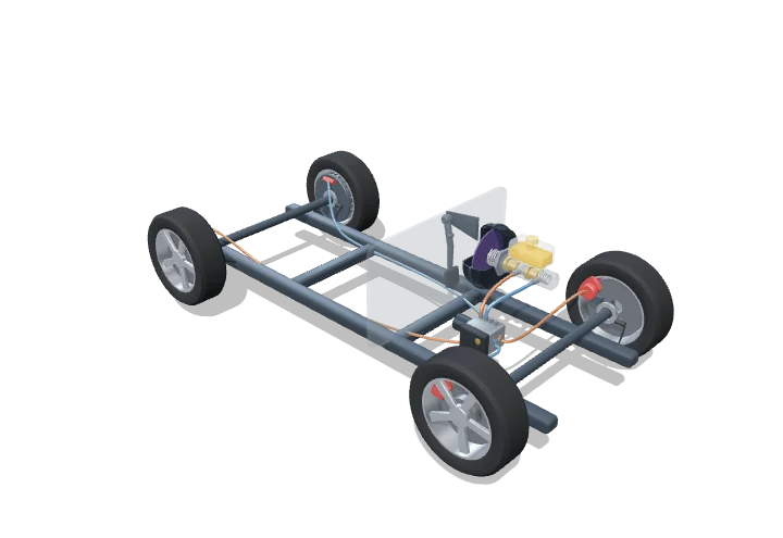 Open the interactive 3D model →
How does a gentle push of your foot stop a 1.3-tonne car rolling at motorway speed?
When you press the brake pedal, a lever and a booster multiply your push and drive a piston into a cylinder full of brake fluid. The fluid cannot be squashed, so the same pressure travels down thin pipes to all four wheels. There it pushes on bigger pistons, which squeeze the brake pads with forces of over ten kilonewtons.
A car’s brakes are a hydraulic force multiplier: the pedal lever and vacuum booster turn a modest foot force into a large push on the master-cylinder piston, and the resulting fluid pressure, transmitted equally through the lines by Pascal’s principle, acts on much larger caliper and wheel-cylinder pistons at the wheels. Two independent circuits provide redundancy, and the ABS unit limits each wheel’s pressure so the tyres keep rolling at the edge of grip.
Key facts
- Pedal ratio (model)
- 3.75 : 1
- Booster assist (model)
- ×4 overall, run-out at 3.2 kN of assist
- Master cylinder bore
- 22.2 mm (⅞ in), A = 387 mm²
- Front caliper piston
- 54 mm, A = 2290 mm² (≈ 5.9 × master cylinder)
- Line pressure for 120 N pedal force
- ≈ 47 bar
- Circuits
- 2, diagonal split (FL+RR, FR+RL)
Parts you can explore (11)
- Brake pedal
- Vacuum booster
- Master cylinder
- Fluid reservoir
- Brake lines
- ABS modulator
- Front disc brakes
- Rear drum brakes
- Wheels
- Wheel-speed sensors
- Chassis
In the 3D model
Rotate and take apart the model, follow a guided tour of what each part does and why it’s needed, change it with a live slider, and test yourself with a short quiz. Free, no sign-up.
Open Hydraulic brake system in 3D →
OpenArc Models’ models are simplified teaching schematics. Terms · Privacy