Fluids & heat
Shell-and-tube heat exchanger
Thermal · Counter-flow heat transfer
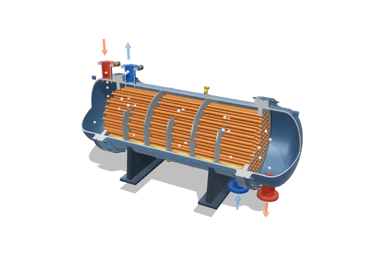 Open the interactive 3D model →
How can a power station cool a river’s worth of steam without the water and steam ever touching?
A heat exchanger moves heat from a hot liquid to a cold one while keeping them apart. The hot water flows inside dozens of thin metal tubes, and the cold water flows around the outside of those tubes. Heat soaks through the tube walls, but not a drop of either liquid crosses over.
A shell-and-tube heat exchanger transfers heat between two fluids separated by thin tube walls, with one fluid inside the tubes and the other guided across them by baffles in the shell. Its duty is predicted from Q = UA·ΔT_lm (LMTD method) when terminal temperatures are known, or from the effectiveness–NTU method when only the inlet temperatures are known.
Key facts
- Overall coefficient U, water–water
- ≈ 850–1,700 W m⁻² K⁻¹
- Overall coefficient U, water–oil
- ≈ 110–350 W m⁻² K⁻¹
- Common tube size
- 19.05 mm (¾ in) or 25.4 mm (1 in) OD
- Tube pitch
- ≈ 1.25–1.5 × tube OD
- Baffle cut and spacing
- Cut ≈ 20–35% of shell ID; spacing ≈ 0.2–1.0 shell ID
- Design standard
- TEMA (Tubular Exchanger Manufacturers Association); the model is a type BEM
Parts you can explore (12)
- Shell
- Tube bundle
- Baffles
- Baffle tie rods
- Tube sheets
- Channel heads
- Nozzles
- Flanges & bolts
- Support saddles
- Vents, drains & thermowells
- Hot stream
- Cold stream
In the 3D model
Rotate and take apart the model, follow a guided tour of what each part does and why it’s needed, change it with a live slider, and test yourself with a short quiz. Free, no sign-up.
Open Shell-and-tube heat exchanger in 3D →
OpenArc Models’ models are simplified teaching schematics. Terms · Privacy