Mechanisms
Harmonic drive (strain-wave gear)
Machines · Precision gearing
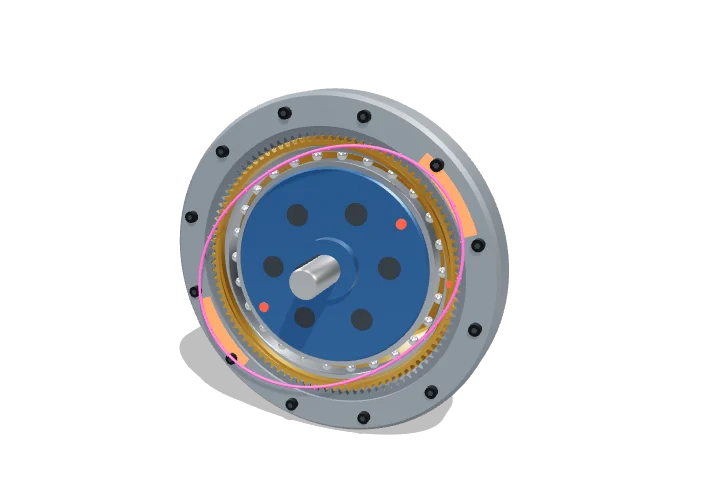 Open the interactive 3D model →
How can a gear made of a bendy steel cup slow a motor down 100 times in a space smaller than a fist?
A harmonic drive has a thin steel cup with teeth round its rim, sitting inside a rigid ring with two more teeth. An oval plug spins inside the cup and squeezes it into an oval, so its teeth mesh with the ring only at two opposite places. Each time the plug turns once, the cup creeps back by just two teeth — so the output turns very slowly but very strongly.
A harmonic drive gets a large speed reduction from three coaxial parts: an elliptical wave generator that flexes a thin toothed cup, so that it meshes with a rigid internal-toothed ring only at the two ends of the ellipse. Because the ring has two more teeth than the cup, each input revolution walks the cup back by two teeth, giving ratios of about 30:1 to 160:1 in one stage with almost no backlash.
Key facts
- Tooth difference
- Z_c − Z_f = 2 (one per lobe of the ellipse)
- Single-stage ratios
- ≈ 30:1 to 160:1 (up to ≈ 320:1 in some designs)
- Backlash
- near zero; lost motion typically < 1 arc-minute
- Teeth in contact
- up to ≈ 30 % of all teeth at once
- Radial deflection
- one module = 2/Z_f of the pitch radius (≈ 3 % at 30:1, 1 % at 100:1)
- Efficiency
- ≈ 60–90 %, falling at low temperature and light load
Parts you can explore (9)
- Wave generator cam
- Flexible bearing
- Flexspline
- Circular spline
- Input shaft
- Output flange
- Engagement zones
- Deformation indicator
- Mounting bolts
In the 3D model
Rotate and take apart the model, follow a guided tour of what each part does and why it’s needed, change it with a live slider, and test yourself with a short quiz. Free, no sign-up.
Open Harmonic drive (strain-wave gear) in 3D →
OpenArc Models’ models are simplified teaching schematics. Terms · Privacy