Mechanisms
Centrifugal (flyball) governor
Control · Negative feedback
 Open the interactive 3D model →
How did a steam engine keep a steady speed long before anyone had electronics?
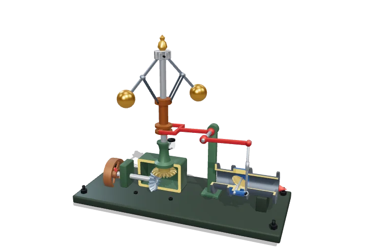
A flyball governor is a speed-keeper made of spinning weights. When the engine speeds up, the weights swing outwards and, through a lever, partly close the steam valve, so the engine slows down. When it slows, the weights drop and the valve opens again.
The centrifugal governor measures engine speed with spinning weights and uses their outward swing to close the throttle, holding speed nearly constant as load changes. It is the classic example of proportional negative feedback, and its tendency to oscillate (“hunt”) prompted Maxwell’s 1868 paper that founded the mathematical theory of control stability.
Key facts
- Equilibrium (Watt)
- tan α = ω²r/g; cone height h = g/ω²
- Model arms
- l = 250 mm, pivots 15 mm off the axis, stops at 25°–60°
- Model speed range
- ≈ 60 rpm (90% load) to ≈ 75 rpm (10% load)
- Minimum speed to lift balls (ideal)
- ω = √(g/l) ≈ 6.3 rad/s ≈ 60 rpm for l = 250 mm
- Typical droop, modern generator governors
- ≈ 4–5% from no load to full load
- Control action
- Proportional, negative feedback
Parts you can explore (10)
- Spindle
- Flyballs & arms
- Sleeve & links
- Throttle lever
- Throttle rod
- Throttle valve
- Drive gear & base
- Drive pulley
- Column & bearings
- Base anchor bolts
In the 3D model
Rotate and take apart the model, follow a guided tour of what each part does and why it’s needed, change it with a live slider, and test yourself with a short quiz. Free, no sign-up.
Open Centrifugal (flyball) governor in 3D →
OpenArc Models’ models are simplified teaching schematics. Terms · Privacy