Fluids & heat
External gear pump
Fluid power · Positive-displacement pump
 Open the interactive 3D model →
How can two plain gears spinning together push oil hard enough to lift a digger’s arm?
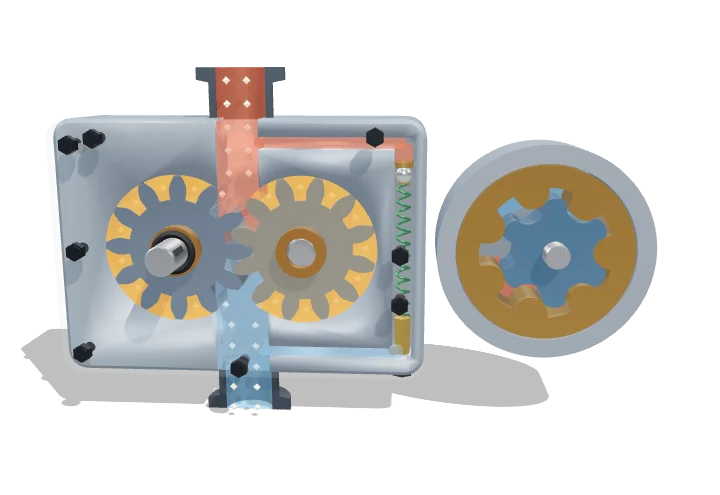
A gear pump has two gears that turn against each other inside a snug case. Oil gets trapped in the gaps between the teeth and is carried round the outside of each gear, then squeezed out where the teeth mesh again. Every turn moves the same amount of oil, so spinning faster pumps more.
An external gear pump is a positive-displacement machine: oil trapped in the tooth spaces is carried around the outside of two meshing gears, and the re-meshing teeth force it out of the outlet. Flow is fixed by displacement and shaft speed, while pressure is set by the load, so a relief valve must cap it.
Key facts
- Displacement (this model)
- ≈ 9.5 cm³/rev (m = 3 mm, z = 12, b = 14 mm)
- Typical displacements
- ≈ 1–250 cm³/rev
- Typical pressures
- ≈ 150–280 bar continuous for industrial/mobile units
- Typical speeds
- ≈ 500–4000 rpm
- Volumetric efficiency
- ≈ 85–98 %, falling with pressure and oil temperature
- Overall efficiency
- ≈ 80–90 % at rated point
Parts you can explore (14)
- Pump housing
- Front cover
- Drive gear
- Driven gear
- Drive shaft
- Shaft bushings
- Inlet port
- Outlet port
- Fluid pockets
- Flow tracers
- Relief valve
- Gerotor inner rotor
- Gerotor outer rotor
- Gerotor housing and ports
In the 3D model
Rotate and take apart the model, follow a guided tour of what each part does and why it’s needed, change it with a live slider, and test yourself with a short quiz. Free, no sign-up.
Open External gear pump in 3D →
OpenArc Models’ models are simplified teaching schematics. Terms · Privacy