Fluids & heat
Gate, globe and ball valves
Fluid systems · Isolation and control valves
 Open the interactive 3D model →
Why do engineers use three different kinds of valve just to turn water on and off?
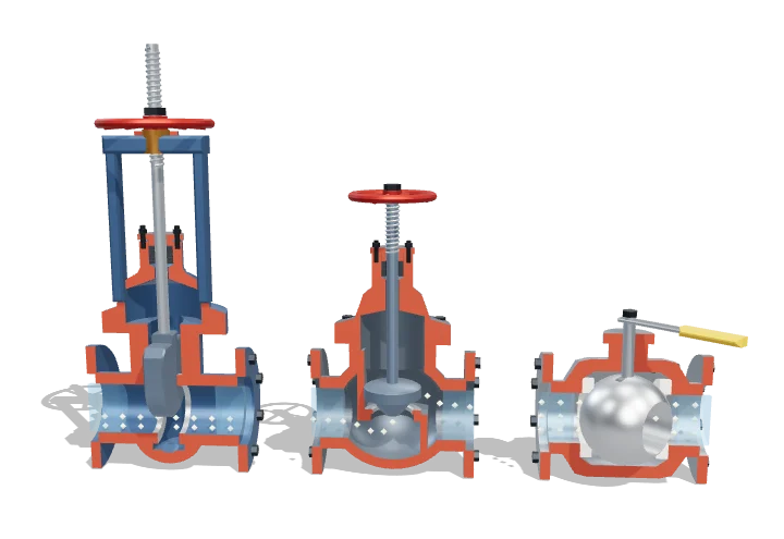
A valve is a tap for a pipe. A gate valve slides a metal wedge across the pipe, a globe valve presses a plug onto a hole, and a ball valve turns a ball with a hole through it. Each shape is good at a different job: shutting off completely, or carefully controlling how much flows.
Gate, globe and ball valves all stop flow, but they do it differently: a wedge slides across the bore, a plug presses onto a seat, or a drilled ball turns a quarter turn. Those geometries give very different pressure losses and inherent flow characteristics, which is why gates and balls are used for isolation and globes for throttling.
Key facts
- Size (this model)
- DN50 (≈ 2 in) bore
- Cv fully open, DN50 (Crane TP-410 K values)
- gate ≈ 330, globe ≈ 50, full-port ball ≈ 535 gpm/√psi
- Loss coefficient fully open
- gate ≈ 0.15–0.2, globe ≈ 6–10, full-port ball ≈ 0.05
- Operation
- gate ≈ 10 handwheel turns, globe ≈ 3–5 turns, ball ¼ turn
- Inherent characteristic
- gate: most Cv gained in the last third of travel · globe (contoured plug): linear · ball: slow then steep, ≈ equal-percentage
- Kv–Cv conversion
- Kv (m³/h at 1 bar) = 0.865 Cv
Parts you can explore (14)
- Gate valve body
- Gate bonnet and yoke
- Gland packing
- Wedge gate
- Rising stem
- Gate handwheel
- Globe valve body
- Globe bonnet
- Globe plug and stem
- Seat rings
- Ball valve body
- Ball
- Ball stem and lever
- Flow tracers
In the 3D model
Rotate and take apart the model, follow a guided tour of what each part does and why it’s needed, change it with a live slider, and test yourself with a short quiz. Free, no sign-up.
Open Gate, globe and ball valves in 3D →
OpenArc Models’ models are simplified teaching schematics. Terms · Privacy