Mechanisms
Four-bar linkage
Mechanisms · Planar linkages
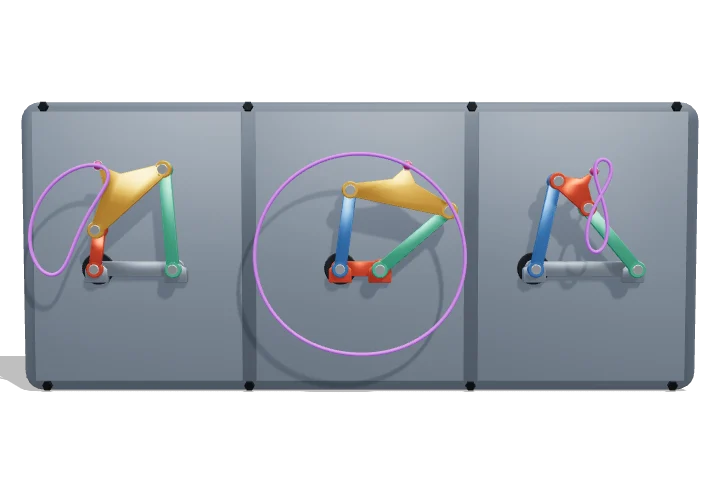 Open the interactive 3D model →
How can four sticks and four pins make a windscreen wiper sweep, a pump nod and a robot leg walk?
A four-bar linkage is four stiff bars joined in a loop by four pins, with one bar held still. Turn one bar and every other bar is forced to move in a definite way. Which bar you hold still, and how long the bars are, decides whether the others spin all the way round or only swing back and forth.
A four-bar linkage is the simplest closed-loop mechanism: four rigid links joined by four pin joints, with one degree of freedom, so a single input angle fixes the position of every link. Grashof’s condition on the link lengths, together with the choice of which link is fixed, decides whether the input and output can turn fully (crank) or only swing (rocker), and a point on the coupler traces a coupler curve whose shape is the main design tool of linkage synthesis.
Key facts
- Mobility (Gruebler)
- M = 3(4 − 1) − 2·4 = 1
- Grashof condition
- s + l ≤ p + q
- Inversions of one Grashof chain
- 2 crank-rockers, 1 double-crank, 1 double-rocker
- Model chain
- {r, 0.8, 0.9, 1.0} × 0.64 units, r = 0.2–0.78
- Grashof limit in the model
- r = 0.7 (s + l = p + q = 1.7)
- Recommended minimum transmission angle
- ≈ 40°
Parts you can explore (9)
- Crank-rocker
- Double-crank
- Double-rocker
- Ground links
- Input drives
- Joint pins
- Coupler points
- Coupler curves
- Base plate
In the 3D model
Rotate and take apart the model, follow a guided tour of what each part does and why it’s needed, change it with a live slider, and test yourself with a short quiz. Free, no sign-up.
OpenArc Models’ models are simplified teaching schematics. Terms · Privacy