Mechanisms
Hydraulic excavator
Machines · Hydraulic linkages
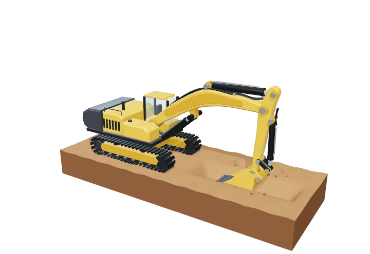 Open the interactive 3D model →
How can an excavator’s arm lift a car-sized bucket of soil using nothing but oil?
An excavator’s arm has three parts — boom, stick and bucket — joined by pins like your shoulder, elbow and wrist. Each joint is moved by its own hydraulic cylinder: oil pumped in under high pressure pushes a piston out with a force of hundreds of kilonewtons. By moving the three cylinders together, the operator makes the bucket dig, lift and dump.
A hydraulic excavator positions its bucket with a planar linkage of three pinned members — boom, stick and bucket — each driven by its own hydraulic cylinder. Pascal’s principle turns oil pressure into cylinder forces of hundreds of kilonewtons, and the linkage geometry turns those straight-line pushes into rotations that cut, carry and dump soil.
Key facts
- Operating mass (20 t class)
- ≈ 20–23 t
- Maximum digging depth
- ≈ 6–6.7 m
- Maximum reach at ground level
- ≈ 9.5–10 m
- Hydraulic system pressure
- ≈ 32–35 MPa (320–350 bar)
- Bucket digging force (ISO 6015)
- ≈ 130–160 kN
- Bucket capacity
- ≈ 0.8–1.3 m³
Parts you can explore (14)
- Ground
- Crawler tracks
- Slewing ring
- Upper structure
- Operator cab
- Boom
- Stick
- Bucket
- Bucket linkage
- Boom cylinder
- Stick cylinder
- Bucket cylinder
- Hydraulic hoses
- Pivot pins
In the 3D model
Rotate and take apart the model, follow a guided tour of what each part does and why it’s needed, change it with a live slider, and test yourself with a short quiz. Free, no sign-up.
Open Hydraulic excavator in 3D →
OpenArc Models’ models are simplified teaching schematics. Terms · Privacy