Mechanisms
Slider-crank mechanism
Kinematics · Rotary ↔ reciprocating
 Open the interactive 3D model →
How does a spinning wheel push a piston straight back and forth — and why can it get stuck?
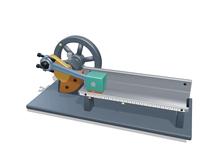
A crank is an arm that turns in a circle. A connecting rod joins it to a slider that can only move in a straight line. Each turn of the crank pushes the slider out and pulls it back once — the same trick that turns pistons into turning wheels in a car engine.
The slider-crank converts continuous rotation of a crank into reciprocating straight-line motion of a slider, or the reverse, and is the core mechanism of piston engines, compressors and presses. Because the connecting rod has finite length, the slider’s motion is not a pure cosine: it moves faster and accelerates harder near the outer dead centre than near the inner one.
Key facts
- Model geometry
- r = 45 mm; rod L = 135–270 mm (L/r = 3–6, default 3.2 → 144 mm)
- Stroke
- 2r = 90 mm, whatever the rod length
- Automotive rod ratio L/r
- ≈ 3–4
- Peak piston acceleration (car engine at red line)
- ≈ 15 000–25 000 m/s²
- Mean piston speed limit (cars)
- ≈ 20–25 m/s
- Degrees of freedom
- 1 (4 links, 3 revolute + 1 prismatic joint)
Parts you can explore (10)
- Crank
- Counterweight
- Connecting rod
- Rod bearings
- Slider
- Slider wear pads
- Guide rails
- Frame & bearing
- Flywheel
- Stroke scale
In the 3D model
Rotate and take apart the model, follow a guided tour of what each part does and why it’s needed, change it with a live slider, and test yourself with a short quiz. Free, no sign-up.
Open Slider-crank mechanism in 3D →
OpenArc Models’ models are simplified teaching schematics. Terms · Privacy