Mechanisms
CNC milling machine
Mechanisms · Manufacturing
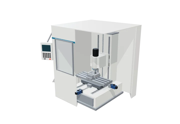 Open the interactive 3D model →
How does a computer carve a solid block of metal into a precise part, to within the width of a hair?
A CNC mill is a machine that follows a computer program to cut metal. A fast-spinning cutter shaves off tiny chips while motors slide the metal block left, right, forwards and backwards and move the cutter up and down. Because the motors are told exactly where to go, the machine can make the same part again and again to a few thousandths of a millimetre.
A computer numerically controlled (CNC) milling machine removes material with a rotating cutter while servo-driven axes move the workpiece and tool along programmed paths. Its accuracy comes from stiff castings, preloaded linear guides, ball screws and closed-loop servo control.
Key facts
- Axes
- X (table), Y (saddle), Z (spindle head)
- Ball-screw lead (model)
- 10 mm per revolution
- Typical positioning accuracy
- ≈ ±0.005 mm; repeatability ≈ ±0.002–0.003 mm
- Model spindle and feed
- 8000 rpm, 1200 mm/min cutting, 15 m/min rapids
- Pocket in the model
- 182 × 121 × 36 mm in 3 levels, 33 mm end mill
- Model program time
- ≈ 2.6 min (ideal, no acceleration limits)
Parts you can explore (12)
- Base
- Column
- Saddle
- Table
- Linear guides
- Ball screws
- Servo motors
- Spindle head
- Cutting tool
- Workpiece and vise
- Enclosure
- Control panel
In the 3D model
Rotate and take apart the model, follow a guided tour of what each part does and why it’s needed, change it with a live slider, and test yourself with a short quiz. Free, no sign-up.
Open CNC milling machine in 3D →
OpenArc Models’ models are simplified teaching schematics. Terms · Privacy