Fluids & heat
Reciprocating air compressor
Fluid power · Slider-crank compressor
 Open the interactive 3D model →
How does a workshop compressor cram enough air into a tank to drive a nail gun all afternoon?
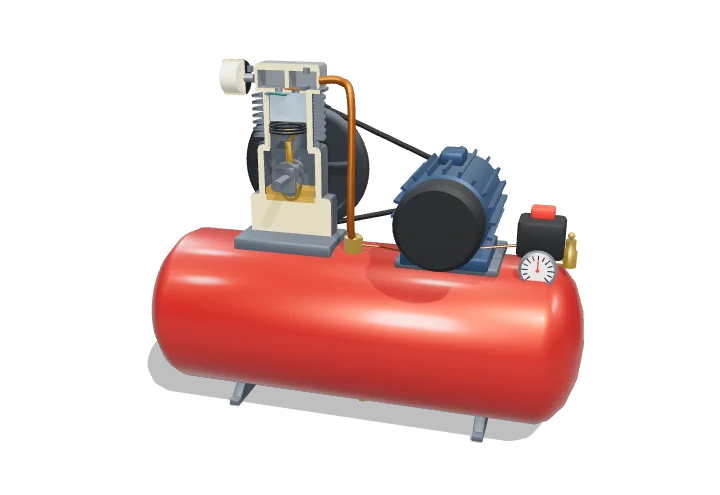
An electric motor turns a crank that moves a piston up and down in a cylinder. On the way down the piston draws air in through a flap valve; on the way up it squeezes the air and pushes it through a second flap into a strong steel tank. Squeezing air makes it hot, and a switch stops the motor when the tank is full.
A reciprocating compressor uses a slider-crank to drive a piston that draws air in through one reed valve, compresses it polytropically, and pushes it through a second valve into a receiver. The compression work, discharge temperature and volumetric efficiency all depend on the pressure ratio and the polytropic exponent, which is why high pressures are reached in cooled stages.
Key facts
- Typical single-stage pressure
- Up to ≈ 8–10 bar gauge
- Polytropic exponent n
- ≈ 1.2–1.35 for small air-cooled cylinders (adiabatic k = 1.4)
- Clearance ratio
- ≈ 3–10% of swept volume (model: 5%)
- Single-stage discharge temperature
- ≈ 150–250 °C at 7–9 bar g
- Model pump
- Bore 70 mm, stroke 50 mm, rod 105 mm, on a 50 L receiver
- Input energy rejected as heat
- Most of it — commonly quoted ≈ 80–90%
Parts you can explore (14)
- Cylinder & head
- Piston
- Connecting rod
- Crankshaft & pulley
- Crankcase
- Reed valves
- Cylinder air
- Intake filter
- Discharge check valve
- Receiver tank
- Pressure switch
- Receiver gauge
- Receiver relief valve
- Electric motor & belt
In the 3D model
Rotate and take apart the model, follow a guided tour of what each part does and why it’s needed, change it with a live slider, and test yourself with a short quiz. Free, no sign-up.
Open Reciprocating air compressor in 3D →
OpenArc Models’ models are simplified teaching schematics. Terms · Privacy